Display Brightness issue
Printed From: Avidyne
Category: Avidyne General
Forum Name: IFD 5 Series & IFD 4 Series Touch Screen GPS/NAV/COM
Forum Description: Topics on Avidyne's IFD 5 Series and IFD 4 Series Touch Screen GPS/NAV/COM
URL: http://forums.avidyne.com/forum_posts.asp?TID=622
Printed Date: 17 Jul 2025 at 9:51pm
Software Version: Web Wiz Forums 12.01 - http://www.webwizforums.com
Topic: Display Brightness issue
Posted By: pburger
Subject: Display Brightness issue
Date Posted: 02 Apr 2015 at 9:33pm
|
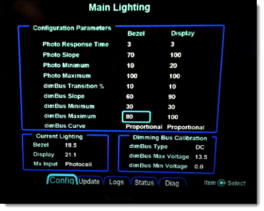
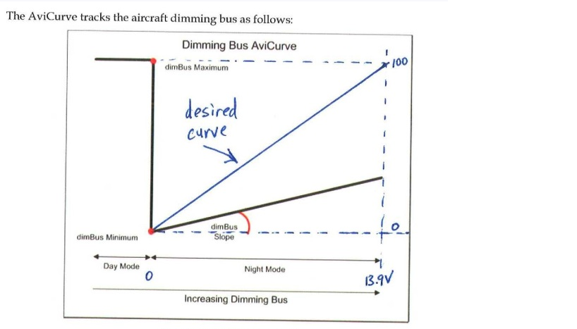
Steve and others, I'm still having a problem getting my display brightness set correctly. I want to use the dimBus with the AviCurve. I want the display to be 100% bright when the dimBus is at 0V, but then as I increase it, I want it to go to the minimum and then ramp back up to 100% at the max dimBus voltage. The following photo shows what I want to accomplish:  I have set the min dimBus voltage to 0, and the max dimBus voltage to 12.9. I set the dimBus minimum to 1 and the dimBus maximum to 100. When I turn the dimBus all the way to the max (12.9V in this case -- on the ground, engine running at idle), I only get 21.3 on the display. I want 100%. How would I set this up? What exactly is the equation? I have played with the slope value, and in this case have it set to the maximum of 100. Either I'm doing something wrong, or there is a bug in the system. The maximum is set to 100, but I'm only getting 21.3. What gives? See this picture for the settings. When this picture was taken, the dimBus was just adjusted to the maximum setting which was 12.9V at the time. This picture was very, very dim and hard to read. I had to enhance the brightness and contrast prior to posting to be able to read the values.  |
Replies:
Posted By: pburger
Date Posted: 06 Apr 2015 at 5:03pm
|
BUMP. Steve, can you please look into this? Or at least explain why I can't get 100% brightness? This is my second IFD-540 (my upper right knob was bent when I got the unit back from the factory with mods, so I now have a factory exchange unit.). Both units behaved the same with respect to the brightness issue, so I don't think this is a one-off issue. It's probably operator error, so please tell me where I'm going wrong.... Paul B.
|
Posted By: AviJake
Date Posted: 07 Apr 2015 at 8:41pm
|
Yes, we'll look into it. We're in the Rel 10.1 end-game crush right now so it may be a week before I can send an update. ------------- Steve Jacobson sjacobson@avidyne.com |
Posted By: pburger
Date Posted: 15 Apr 2015 at 11:16am
|
BUMP. This really feels like a bug in the system, but not one other user has chimed in with a similar experience, so perhaps it is operator error. If I can provide any further information I will. Just let me know.
Paul B. |
Posted By: oskrypuch
Date Posted: 15 Apr 2015 at 12:00pm
|
<deleted>
|
Posted By: Bad1996
Date Posted: 15 Apr 2015 at 1:09pm
| Mine is not bright enough at night. Maybe not even with the rheostat adjustment full on but at full on everything else is too bright. I have not attempted changing the 540 settings "yet" |
Posted By: Bad1996
Date Posted: 16 Apr 2015 at 8:54pm
|
Regarding your first question. Today I moved my dimbus minimum voltage from 0 to 6.5 volts (28 v system) and now at the very bottom of the dim on the rheostat the 540 is full bright and then as I brighten via the rheostat the 540 goes dim and then gets brighter. There is a procedure to auto input max and min voltage. When I did my min it started acting this way which sounds like what you want. I never got mine to brighten as much as I need using dim bus but I may be missing a step. User selected brightness isn't bad but as you step thru dim to bright and back, there in the middle is one huge step that to me shouldn't be there. |
Posted By: oskrypuch
Date Posted: 16 Apr 2015 at 10:27pm
|
Generally better to set dimbus transition to 1 or 2, and select proportional instead of avicurve. You really have to set the minimum and maximums accurately, 1v and 28v might be typical. Have a look at a thread I started called display settings, or something like that, probably a couple months ago now. * Orest |
Posted By: pburger
Date Posted: 16 Apr 2015 at 10:27pm
|
The AviCurve is intentionally designed to go to full brightness at the minimum dimbus voltage, as shown in the graph. I get this. To turn my nav lights off, I have to dial my rheostat all the way down and then the nav light switch clicks off. This would be normal for day operation, hence the display going to full bright. However, at night, I turn on my nav lights by clicking the dial, and then I slowly rotate it to get the desired brightness. The problem is that it won't go past about 21%, even though I have the max level set to 100. When above the min dimbus voltage, I would expect the equation to look something like: Display level = (dimBus voltage)/(dimBus max voltage) * (dimbus Maximum) Of course, there is the dimBus slope in there, too. I have that set to 100. I just need someone at Avidyne to show the equation so I know how to set the parameters. Or perhaps to fix the equation if there is a problem with it? |
Posted By: pburger
Date Posted: 16 Apr 2015 at 10:33pm
|
Orest, I didn't see your post before I posted mine. It wasn't in response to yours. I suppose if the transition is set to 1 or 2, that when I dial my dimBus voltage down to zero, the brightness will revert to the photocell? I guess that would work, but I would still need the proportional to be able to be dialed up to 100%. I will try that and report back. |
Posted By: brou0040
Date Posted: 26 Apr 2015 at 5:22pm
|
Now that my unit seems to be responding properly to the dimbus (not confident just yet), mine is acting the same as pburgers. I'm guessing that it's operator error and that I'll need to putz with the settings for awhile. Have you gotten yours working yet? I think I'll want AviCurve instead of proportional because proportional requires me to have the radio lights on full blast all the time to have the 540 lighting turned on. I only turn on the radio backlighting when it's dark out.
|
Posted By: MysticCobra
Date Posted: 27 Apr 2015 at 6:18am
|
I will say this: Setting up the bezel and screen backlighting is the LEAST intuitive thing about the IFD540. Mine's all jacked up along the lines of what others have posted (unexpected step changes in brightness while adjusting the dimmer, not changing brightness at desired "gain" with dimmer, etc.), and I keep forgetting about it until I'm in the air in the dark and get slapped with it again. Until I remember to spend some quality time in the dark with it to see if I can figure out the magic settings, I currently have all the automatic settings overridden and am dialing in the dimmer manually via the "user setting" option, which is somewhat annoying.
|
Posted By: oskrypuch
Date Posted: 27 Apr 2015 at 7:37am
|
I would concur, the lighting settings are a little tricky. I think I now have mine the way I like it, both night and day, and inbetween. * Orest |
Posted By: PA20Pacer
Date Posted: 27 Apr 2015 at 8:10am
|
Hi Orest- I encourage you to share the settings that are working for you. Regards, Bob ------------- Bob Siegfried, II Brookeridge Airpark (LL22) Downers Grove, IL |
Posted By: Don
Date Posted: 27 Apr 2015 at 8:34am
| Orest...... +1 |
Posted By: pburger
Date Posted: 27 Apr 2015 at 11:45am
|
I feel a little better now that others have chimed in... but it's been 20 days since Steve said it might be a week before he could send an update. I realize that 10.1 is a priority, but it sure would be nice to get this straightened out -- either by better explaining how to set up the system, or by identifying the bug and fixing it. |
Posted By: oskrypuch
Date Posted: 27 Apr 2015 at 6:16pm
 Only change from the above pic is that I changed dimbus transition to 3%. Have peek at this thread: http://forums.avidyne.com/forum_posts.asp?TID=529&KW=lighting&title=setups-bezel-display-lighting" rel="nofollow - http://forums.avidyne.com/forum_posts.asp?TID=529&KW=lighting&title=setups-bezel-display-lighting * Orest |
Posted By: brou0040
Date Posted: 28 Apr 2015 at 12:00am
| I think the key is to set the slope and dimBus Max to 100. When I do that, Display is only gets up to 21.3 at max bright, but that was bright enough while in the dark hanger and about right for the radio lighting. I guess that if you leave it off during the day and don't transition until it's significantly dark out, you'd be fine. I'm not sure why the slope doesn't go up to 100%. |
Posted By: pburger
Date Posted: 28 Apr 2015 at 11:54am
|
21.3 was the max I saw, too. You can see it in the photo I posted. I would like it to get to the max that I set (100). That way, I can dial it down to where I want it. Avidyne -- What's going on with this? Why can't we get full brightness?
|
Posted By: brou0040
Date Posted: 28 Apr 2015 at 3:32pm
|
I'm also seeing the odd bezel lighting issue mentioned in the first few posts http://forums.avidyne.com/forum_posts.asp?TID=546&KW=bezel&PID=5146&title=bug-bezel-display-issue#5146" rel="nofollow - here . I can't seem to understand why it would be designed this way and think it would be an improvement to change this so it tracks the bezel lighting.
Are those lights binary on/off without dimming capability? That would seem odd in this application, but I'm trying to understand the design concept.
|
Posted By: pburger
Date Posted: 14 May 2015 at 2:46pm
|
BUMP Steve/Simpson, Has anyone at Avidyne had a chance to look at this? It's been 6 weeks since I posted, and over a month since Steve said he might need a week for a response. (I don't count responses from Orest as official Avidyne responses ;) ) I realize there is a push for 10.1, but that shouldn't shut down technical help for actual users right now. pburger
|
Posted By: AviSimpson
Date Posted: 14 May 2015 at 3:29pm
|
Hey Paul, I just spoke with tech support about your settings and what you are looking to accomplished. They recommend adjusting your dimBus Transition % from 10 to 50. There is a proposed software change that will effect the AviCurve but I don't have the exact details on that. -Simpson ------------- Simpson Bennett Avidyne Corporation Product Manager |
Posted By: pburger
Date Posted: 16 May 2015 at 2:52am
|
Simpson, I changed the dimBus transition to 50, but that had no effect on my original issue, which is that the display will not go to full brightness when on the dimBus, and turned all the way to the max voltage. It only goes to 21.3%. I still don't understand the settings. On the graph I posted, I would think the x-axis would be the dimBus voltage ( min on left, max on right), and the y-axis would be the display brightness (dimBus minimum and dimBus maximum). I would think the "slope" would be determined by those inputs. Why is there a separate Slope parameter? How does the Slope parameter come into play? As I asked in the original post of this thread, "What exactly is the equation?" It is in no way intuitive. Based on Avidyne's lack of a meaningful response to my original question, I guess this truly is a BUG, and the software change that is proposed will fix it? |
Posted By: brou0040
Date Posted: 16 May 2015 at 8:42am
|
I'm not sure it's a bug based on the fact that it shows up in their plot. My guess is they did a bunch of testing in their bat cave or whatever they use for night time testing, but didn't test their design in daylight or transitional lighting. I think it's a design flaw. I'm not sure anyone whose dimmer circuit controls other panel lighting could prefer the AviCurve based on it's current design. Just allow the user to select max (which can go to 100%) and the min (that can go to 0%) and prevent min from being greater than max (and vice versa) and be done with it. Using slope may be mathematically equivalent, but is just odd. If you set the transition at 50%, you'll still get the jump to full bright as you fly into dark environments, it just won't be as big of a shot since it won't be as dark when it transitions. AviSimpson, do you know if the proposed changes are part of 10.1? This has been an issue for a long time and should be an easy fix. I don't recall seeing any argument from Avidyne about why the current design has merit other than work around suggestions so I'd like to think this one isn't under debate.
|
Posted By: pburger
Date Posted: 27 May 2015 at 11:11am
| ....crickets.... |
Posted By: Bad1996
Date Posted: 31 May 2015 at 7:12pm
| Got my 540 back and had a night flight yesterday. I would just like for the user controlled display light to NOT have the huge jump from dim to brighter. What I need is in that "missing" area. I know this has been discussed before but I don't recall a reason being given as to why it is like this ? Thanks |
Posted By: brou0040
Date Posted: 31 May 2015 at 10:09pm
The jump to bright as the dimmer is turned down is to allow the unit to be full bright when the lighting is turned off. The transition can be adjusted. If your lighting works differently, you can use the proportional setting instead of the AviCurve. The missing area issue is that using the AviCurve, the unit can't get bright enough during the day. This makes you rely on the sensor and transition settings, which is not ideal.
|
 Bad1996 wrote:
Posted By: Bad1996
Date Posted: 01 Jun 2015 at 11:59am
|
I'm talking about Manually setting the brightness. AUX/SET-UP/OPTIONS THEN: Display Mode, select "user control" and then right below that you can adjust "display backlight" There is a huge jump right in the middle of the scale. For now I have given up on avicurve and anything using the panel rheostat lighting adjustment. |
Posted By: Bad1996
Date Posted: 02 Jun 2015 at 10:44pm
|
Posted By: Bad1996
Date Posted: 07 Jun 2015 at 12:03am
| Hello ? |
Posted By: Bad1996
Date Posted: 08 Jun 2015 at 11:53pm
|
Posted By: AviJake
Date Posted: 09 Jun 2015 at 7:48am
|
We've been terrible on responding to this thread. Simpson has been all over me to get a comprehensive answer put together. We will. ------------- Steve Jacobson sjacobson@avidyne.com |
Posted By: Bad1996
Date Posted: 09 Jun 2015 at 2:22pm
| Not having the big jump/gap in the user controlled setting would do me for a while. |
Posted By: pburger
Date Posted: 22 Jun 2015 at 3:22pm
Now that 10.1.0.0 is out, when can we expect a "comprehensive answer" to my original question?
|
Posted By: AviJake
Date Posted: 22 Jun 2015 at 3:33pm
|
Sometime in the next few weeks. ------------- Steve Jacobson sjacobson@avidyne.com |
Posted By: ptlevine
Date Posted: 24 Jun 2015 at 1:23pm
| I noticed the same issue last night. Using the "manual" control to dim the screen, it goes from super bright to less super bright (but still bright) at the middle of the indicator. Then it jumps to really too dim from that bright setting and continues down to super dim. Somewhere in the step function change from bright to too dim is my desired setting... |
Posted By: AviJake
Date Posted: 06 Jul 2015 at 9:22am
|
Spent some time refreshing myself on our dimming schemes. Here is a long-winded version/explanation that I've cut and pasted from an internal white paper I wrote on the topic (expect the formatting to be sub-optimal): Dimming Controls Background and Description
We agree that the dimming controls when not set to “User
Control” are hard to use/understand. It
took us quite a while ourselves to understand it as we developed it.
The reason all the parameters exist and the complicated
relationship between them exists is that our premise when designing the
lighting controls was that there were 140,000 installed 530s and 430s and that
installers (and owners) have been using them for many years and would be
familiar with it. Rather than inventing a whole new scheme, we chose to use the
one that we thought the dealer and owner market have been using and learned.
Had we designed our own, there would have been no way we
would have picked this. Nevertheless,
it’s what we chose and what we now have.
We did add the 2nd curve (the “AviCurve”) at my
insistence since if I really were using the cockpit dimming rheostat(s) control
to set cockpit dimming, a typical behavior would be to set it full off in
daytime flying. In that case, I wouldn’t
want my bezel and display to be fully dimmed, hence that jump up to full
daytime brightness when the dimming rheostat is very low.
As a review, here is an excerpt from the 540/440
Installation Manual for dimming controls below.
I’ve highlighted an important section that talks about the transition
point and a recommended technique to use to avoid one operational gotcha that
some folks have noted when they have the “Mx Input” field = Photocell:
+++++++++++
IFD540/440 Installation Manual snippet +++++++++++++++++++++++++
7.5.6 Main Lighting Configuration (Page 5 of 12)The source of the lighting for the IFD5XX/4XX can be the
bezel photocell sensor or the dimming bus.
28VDC, 14VDC, 5VDC and 5VAC dimming buses are all supported and are
automatically detected by the IFD5XX/4XX.
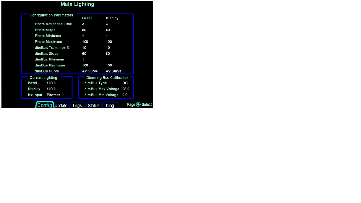 Figure 14: Main Lighting Configuration
Page
Photo Response Time
Sets the speed at which the brightness changes when
photocell is selected as the lighting source. Both the Bezel and Display fields
have a range of 1 to 5, and the factory default is 3.
Photo Slope
The Photo Slope sets the sensitivity of the display/bezel to
changes in the input when the dimming source is the IFD5XX/4XX photocell. This
field has a range of 15 to 100, and the factory default is 80.
Photo Minimum
The Photo Minimum sets the minimum brightness when the
dimming source is the photocell. Both the Bezel and Display fields have a range
of 1 to 50, and the factory default is 1.
Photo Maximum
The Photo Maximum sets the maximum brightness when the
dimming source is the photocell. Both
the Bezel and Display fields have a range of 50 to 100, and the factory default
is 100.
dimBus Transition %
The
dimBus Transition % sets the threshold where the aircraft dimming bus takes
over from the photocell. Below this threshold, the aircraft dimmer controls the
IFD5XX/4XX lighting. Both the Bezel and Display fields have a range of 0 to
100, and the factory default is 10.
Note:
If it is not desired to hand brightness control over to the dimming bus from
the photocell at any point, set dimBus Transition % to 0 (zero). Doing so will prevent the scenario where, in
increasingly darker environments (e.g. flying past sunset into dark night), the
display automatically dims and dims and dims and then suddenly jumps to bright.
dimBus Slope
The dimBus Slope sets the sensitivity of the display/bezel
to the aircraft dimmer. Both the Bezel and Display fields have a range of 15 to
100, and the factory default is 60.
dimBus Minimum
The dimBus Minimum sets the minimum brightness when the
aircraft dimmer is the dimming source. Both the Bezel and Display fields have a
range of 1 to 50, and the factory default is 1.
dimBus Maximum
The dimBus Maximum sets the maximum brightness when the
aircraft dimmer is the dimming source.
Both the Bezel and Display fields have a range of 50 to 100, and the
factory default is 100.
dimBus Curve
The dimBus Curve sets the aircraft dimming bus to either a
Proportional Curve or AviCurve on the IFD5XX/4XX.
The Proportional Curve tracks the aircraft lighting bus as
follows: Maximum night lighting at maximum aircraft lighting bus voltage,
Minimum night lighting at minimum aircraft lighting bus voltage (linear
in-between).
The AviCurve tracks the aircraft dimming bus as follows:
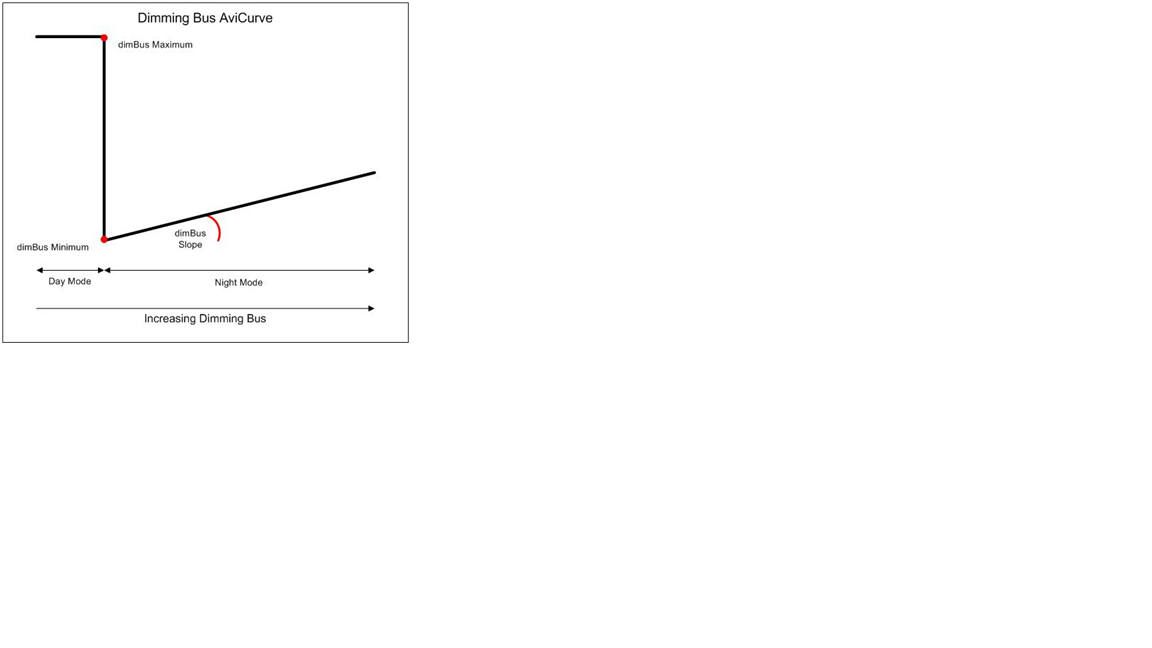 Figure 15: Lighting Curve - AviCurve
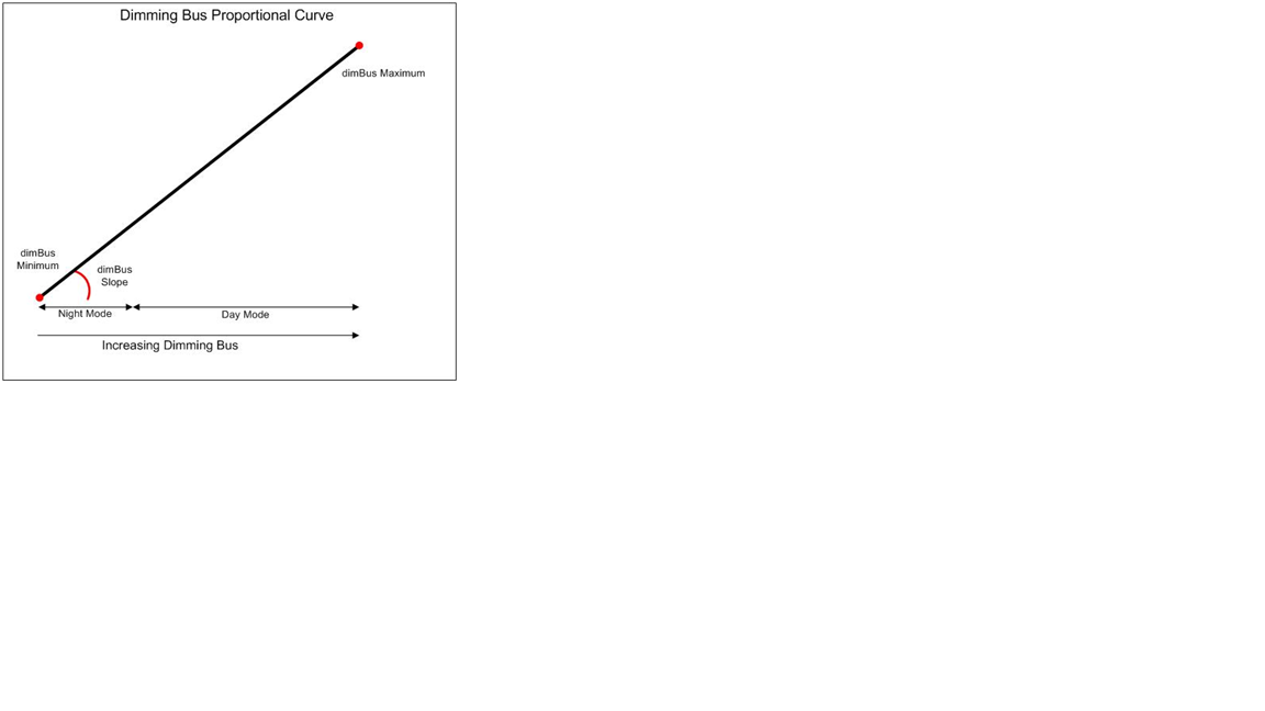 Figure 16: Lighting Curve -
Proportional Curve
Table 83: Lighting Bus Configuration
Dimming Bus
Calibration
The section will calibrate the IFD5XX/4XX to the aircraft
avionics lighting bus.
Table 84: Lighting Bus Configuration
To calibrate the dimming bus:
Repeat the process for the minimum value (use full
counter-clockwise position of rheostat)
++++++++++++
End of IFD540/440 Installation Manual snippet +++++++++++++++++++++
We are aware of two operational issues that folks have
noticed/squawked about in the time the IFD540 has been fielded.
One of the questions/scenarios folks are asking is why a
100% slope value doesn’t result in 100% brightness value. This was intentionally done through a lot of
empirical testing in a darkroom and during night flight tests. However, field experience has shown a wider
breadth of aircraft lighting configurations than had been anticipated and we are
looking into making a change in the software in an upcoming release to enhance the behavior of the
AviCurve. In that potential change,
setting a dimBus slope of 100 will result in maximum brightness instead of the
21%ish that can currently be achieved.
This should achieve the desired curve at the beginning of this thread
(copied below for completeness).
 The second operational gotcha observed is an
unexpected/undesired flashing or sudden increase of display/bezel brightness as
the dimming bus controls (e.g. rheostat) are adjusted lower. That is covered by the bold
text above and can be avoided by adjusting the dimBus Transition % parameter
down close to, or at, zero.
------------- Steve Jacobson sjacobson@avidyne.com |
Posted By: hamilton
Date Posted: 16 Jul 2015 at 12:01am
|
Thanks AviJake, If the 'proportional' curve went to photocell on 0V (or near) the system would be a lot more usable than it currently is. AviCurve needs to respond as the majority of other avionics systems do or it won't be used, i.e. full volts - full bright. Any broad guess as to when a lighting update would come out of the pipeline so we can update customers?
|
Posted By: pburger
Date Posted: 16 Jul 2015 at 11:22am
|
Steve, I appreciate your response to this issue and the work on a potential change that will allow full brightness when using the dimBus. However - something just doesn't seem right with the explanation. I'm not trying to call you out, but rather, I'm just trying to understand the issue. I just can't get my engineer mind around this. A few things: 1. Why is there a dimBus slope at all? The following parameters define the slope:
2. You say that the max brightness was determined based upon "a lot of empirical testing in a darkroom". But there is a configurable parameter for max brightness, so why would you ignore that and clamp it at 21.3%? Sure, you might recommend setting the max to 21.3 based on testing, but why clamp it there? Something doesn't feel right about this explanation. 3. If I am thinking about this right, I assume the bezel should get brighter as the ambient light gets dimmer. However, for the display, it should work just the opposite: the display should be at it's brightest during the day, and get dimmer as the ambient light gets dimmer. If I put both display and bezel on photocell will they work this way? I will mess around with that and see. All of the above aside, and after much thoughtful consideration, I think what I really want is the following: Right now I am adjusting the brightness in manual mode, which is a pain in the rear to go into the menus and dial the brightness to the desired level prior to and during every night flight. I do this for both the display and the bezel. I think I would like the display brightness to always operate on the photocell. To accomplish this I will put the Photo Maximum at the highest brightness that I feel is necessary during a bright sunny day. I will put the Photo Minimum at the dimmest setting for the darkest cockpit situation. I think I need to put the dimBus transition % to 0 to keep the display on the photocell. I plan to try this out soon, and will report back. (However, Plan B will be to use the dimBus if I am unable to get the system configured to my liking with the photocell) I think I would like the bezel to operate on my dimBus, like all my other radio lights. I may just use the proportional curve for that, because during the day, I don't need those buttons illuminated. As long as I can configure the min and max brightness for the bezel, I guess I'll be okay. I will have to see if the bezel behaves the same as the display on the dimBus (i.e. - the 21.3% arbitrary maximum). If so, I sure hope Avidyne fixes that. Paul B. |
Posted By: AviJake
Date Posted: 16 Jul 2015 at 5:13pm
|
Hi Paul, 1. We matched the Garmin design under the premise that 140,000 owners or installers had experience using that design and thought that taking that approach would be better. We were wrong but we have what we have now. And yes, we got bogged down with the dimBus slope parameter - the amount of time we spent on this dimming stuff during development was mind boggling (and in hindsight, perhaps a complete waste of time). 2. Sorry, but true. 3. Will be interested to hear your results. And we've completed the change now for the un-clamping of the max brightness. If you set a slope of 100%, you will get 100% brightness. Now under that change, you would have to set a "slope" of 21 to get 21%. This change will come out in the very next IFD software release. ------------- Steve Jacobson sjacobson@avidyne.com |